| Processor Name | ICSP Supported | ICD Supported |
| PIC16F87[0123467] | yes | yes |
| PIC16F87[3467]A | yes | yes |
| PIC16F8[34] | yes | no |
| Command | Description | Examples |
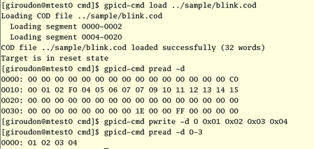
| load hex-file load cod-file |
Load iHEX8 or .COD file into program memory | gpicd-cmd load blink.hex gpicd-cmd load blink.cod |
| load -d hex-file | Load iHEX8 file into EEPROM data memory | gpicd-cmd load -d config.hex |
| pwrite addr word ... | Write one or several word(s) to program memory from address addr | gpicd-cmd pwrite 0 0x000000 |
| pwrite -d addr word ... | Write one or several word(s) to EEPROM data memory from address addr | gpicd-cmd pwrite -d 0 0x01 0x02 |
| pread [-h] | Read and display the whole program memory (option -h dumps program in iHEX8 format). | gpicd-cmd pread -h |
| pread [-h] addr1[-addr2]... | Read and display program memory segments (option -h dumps program in iHEX8 format). | gpicd-cmd pread 0-3 0x2000-0x2007 |
| pread -d [-h] | Read and display the whole EEPROM data memory (option -h dumps data in iHEX8 format). | gpicd-cmd pread -d |
| pread -d [-h] addr1[-addr2]... | Read and display EEPROM data memory segments (option -h dumps data in iHEX8 format). | gpicd-cmd pread -d 0x00 0x10-0x1F |

In interactive mode, the command set listed in the previous table are still available. You can
also
use some additional ICD-oriented commands:
| Command | Description |
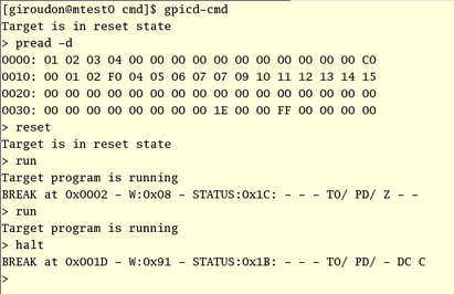
| reset |
Put the target processor in Reset state |
| halt | Halt the target program. Ignored if the target is not Running. |
| run | Start (after reset) or Resume (after halt or breakpoint) program execution. Ignored if the target is not Halted or Resetted. |
| step | Execute the next instruction and halt. Ignored if the target is not Halted. |
| brk clear | Clear the current breakpoint. Ignored if the target is not Halted. |
| brk addr |
Put a breakpoint at address addr. Ignored if the target is not Halted. |
| freeze on|off |
Enable/disable peripheral freeze mode for ICD operation |
| read addr |
Read file register at address addr |
| write addr value
|
Write a 8-bits value to
file regiter at address addr |
| verbose on|off |
Change verbosity mode. When verbose mode is
enabled, all ICSP/ICD operations that are performed to the target are
displayed. |
| config [kw [args]] | Manage target configuration word (see the target configuration table below) |
| icsp [field:value]
... |
Set and Show ICSP hardware
interface configuration. The configuration settings are automatically saved in file .gpicd in the user's home directory. Available configuration fields are listed in the ICSP configuration table below. |
| exit |
Exit the GPICD command line interpreter |

| Command | Description |
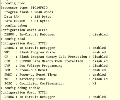
| config proc [type] |
If type is specified, select this
processor type. Show current processor type. Available processor types are listed here. |
| config debug [enable|disable] |
Set and show debug mode (processor types PIC16F87x[A] only). |
| config wrt [mode] |
Set and show flash program write mode. - For PIC16F87x : mode = { enable, disable } - For PIC16F87xA : mode = { enable, half,quarter,256 } |
| config cp [mode] |
Set and show Flash Program Memory Code Protection mode. - For PIC16F87[3467] : mode = { enable, disable } - For other processor types : mode = { enable, half,256, disable } |
| config cpd [enable|disable] | Set and show EEPROM Data Memory Code Protection mode. |
| config lvp [enable|disable] |
Set and show Low-Voltage Programming mode (processor types
PIC16F87x[A] only). |
| config bor [enable|disable] |
Set and show Brown-Out Reset mode. |
| config pwrt [enable|disable] |
Set and show Power-Up Reset Timer mode. |
| config wdt [enable|disable] |
Set and show Watchdog
Timer mode. |
| config fosc [rc|hs|xt|lp] |
Set and show Oscillator mode. |
| config read | Read and show configuration word from target. |
| config write | Write configuration word to target. |
| config erase [enable|disable] | Set and show 'Bulk-Erase before programming' option |
| config download [enable|disable] | Set and show 'Download Debug Monitor' option |

| Field Name | Possible Values | Description |
| dev |
/dev/parportN |
Parport device name. This device
is implemented by the ppdev kernel module (which is Linux native) |
| type |
GPICD AN589 Custom |
Hardware interface type. GPICD and AN589 are two predefined types. Custom is a user-defined type, configurable using the other fields of this table. |
| mclr |
D0 D1 D2 D3 D4 D5 D6 D7 1 |
Target reset. To be connected to
the MCLR pin. 2 |
| vpp |
D0 D1 D2 D3 D4 D5 D6 D7 1 | Vpp activation. To be connected to the circuitery that enabled Vpp in the MCLR pin. 2 |
| pgd_en | NONE D0 D1 D2 D3 D4 D5 D6 D7 1 |
PGD data signal enable. 2 |
| pgd_out | D0 D1 D2 D3 D4 D5 D6 D7 1 | PGD data output. To be connected to the PGD/RB7 pin. 2 |
| pgd_in | ERROR SELECT PE ACK BUSY 1 | PGD data input. To be connected to the PGD/RB7 pin. 2 |
| pgc_en | NONE D0 D1 D2 D3 D4 D5 D6 D7 1 |
PGC clock signal enable. 2 |
| pgc_out | D0 D1 D2 D3 D4 D5 D6 D7 1 | PGC clock output. To be connected to the PGC/RB6 pin. 2 |
| activity | NONE D0 D1 D2 D3 D4 D5 D6 D7 1 |
Activity LED. To be connected to a LED that flashes when the ICSP/ICD interface is working. 2 |