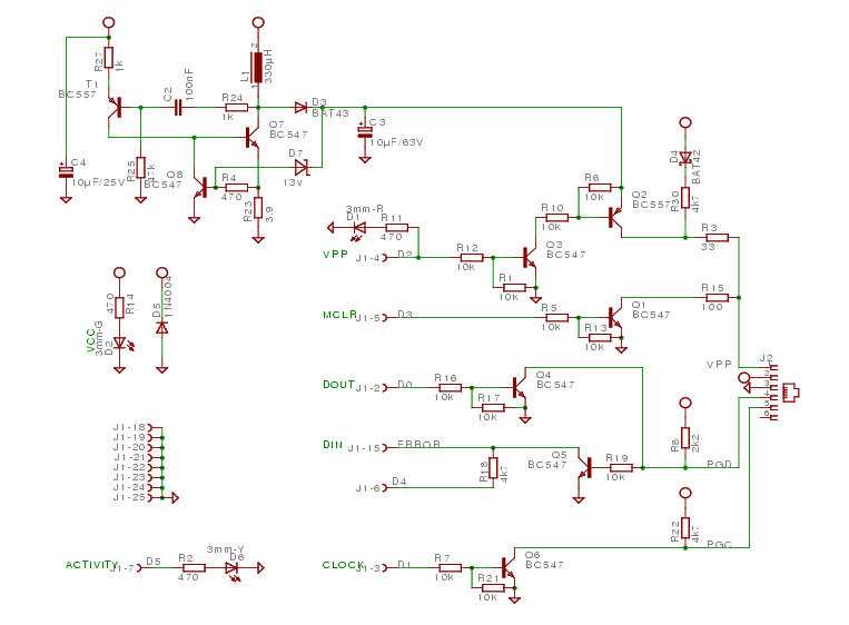
Above is the hardware interface schematics.
The hardware interface schematics and PCB layout are also available for download in
Eagle format.
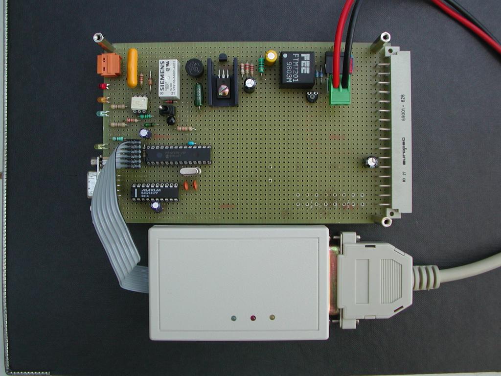
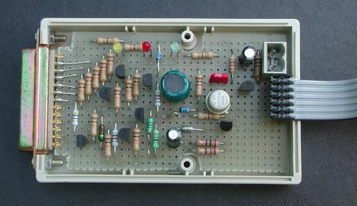
Please note that I never realized the PCB: I only have a hand-wired
board (which is not so difficult to do, given the low number of
components). Here is a picture of my hand-made piece of art...
Five pins of J2 are enough to connect to the target microcontroller.
The following table give the description of the signal available on
this
connector, along with the PIC pin it must be wired to.
| Pin | Description | PIC16F87[0236] |
PIC16F87[147] |
PIC16F8[34] |
| 1 |
MCLR - Driven to 0V (reset), 5V (run) or 13V (program) |
1 |
1 |
4 |
| 2 |
Vdd - 5V Power provided by the target |
20 |
32 |
14 |
| 3 |
Vss - Ground |
8,19 |
12,31 |
5 |
| 4 |
PGD - ICSP/ICD data line |
28 |
40 |
13 |
| 5 |
PGC - ICSP/ICD clock |
27 |
39 |
12 |
Copyright ©
Sylvain
Giroudon 2003
$Revision: 1.7 $
$Date: 2004/12/08 10:04:33 $